
How to Replace a Faulty PacDrive C600?
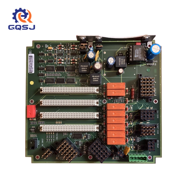
In industrial automation, sudden machine downtime is an absolute nightmare. When a packaging line freezes and a vital motion controller flashes an error code, every minute of delay costs thousands of dollars. The PacDrive C600 Controller by Schneider Electric is a highly reliable system based on an Intel module processor and the VxWorks operating system. However, after years of heavy multi-axis operation, component aging or hardware faults can occur.
When your control panel shows a hardware failure, a precise, structured replacement is the only way to restore your system safely. This step-by-step technical guide is designed for plant maintenance engineers to safely isolate, tag, remove, and replace a faulty Schneider servo controller without losing crucial system parameters.
Section 1: Pre-Replacement Preparation and Safety Protocols
Replacing complex automation hardware requires strict adherence to safety standards. Working inside an active electrical cabinet exposes technicians to dangerous residual voltages, particularly within the servo drive dc bus bars.
1.1 Implement Lockout/Tagout (LOTO) Procedures
Before opening the control cabinet doors, you must completely isolate the machinery from its primary power source. Follow the standard lockout tagout procedure to ensure nobody re-energizes the system while you are manipulating internal wiring. Turn off the main circuit breakers supplying the control panel and secure them with personal safety padlocks and warning tags.
1.2 Identify the Faulty Module
Open the cabinet and locate the target unit. Verify the specific error indicators on the controller’s display or diagnostic interface.

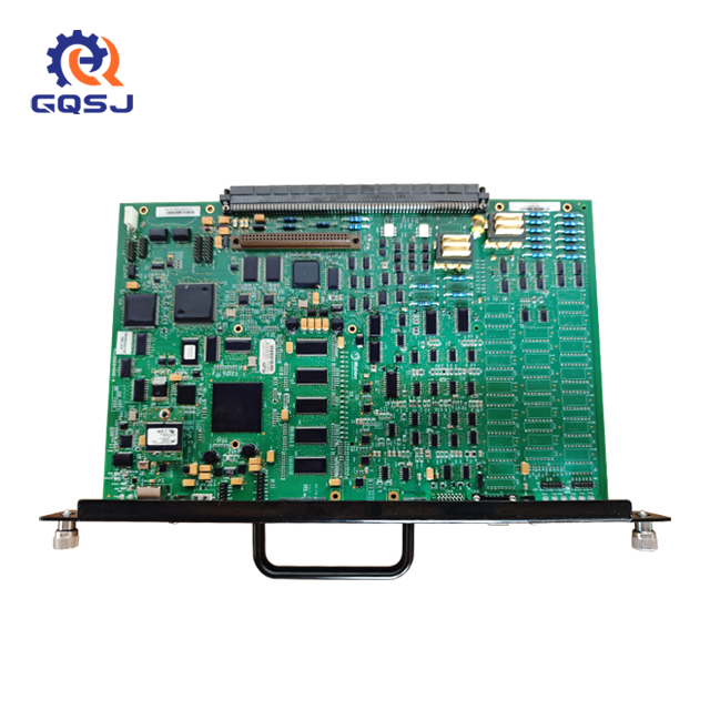
As shown in the technical diagnostic overview, clear marking prevents accidental removal of functional neighbor components like the peripheral I/O modules or secondary power supplies. Place a visible physical tag on the defective controller to maintain absolute clarity during multi-shift operations.
Section 2: Safe Disconnection and Wire Management
The PacDrive C600 acts as a central brain, generating precise servo drive synchronization for up to 99 axes simultaneously. Consequently, it is surrounded by dense, intertwined communication and power cables that must be handled systematically.
2.1 Labeling and Documenting Terminal Blocks
Never rely entirely on memory or original schematic colors when disconnecting wires.
1. Photograph the original terminal layouts using a tablet or camera for reference.
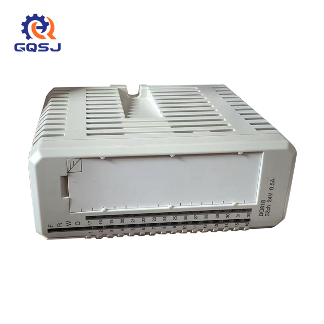
2. Note the positions of the green digital input/output pluggable terminal blocks on the left side of the controller.
3. Unplug the terminal headers carefully by releasing any integrated retention screws. Keep the internal wiring clusters intact within their respective cable trays.
2.2 Unplugging Communication Buses
The C600 controller relies heavily on the SERCOS bus interface to transmit high-speed motion commands to connected servo drives. These fiber optic or specialized copper cables are highly sensitive to sharp bends and debris.
● Disconnect the SERCOS cables gently from their optical rings or RJ45 sockets.
● Cap the fiber optic cable ends immediately to prevent dust contamination, which causes fatal light attenuation and network communication drops.
● Unplug any serial communication lines, Ethernet networks, or master-slave synchronization cables connected to the SUB-D ports.
Section 3: Physical Extraction of the PacDrive C600
Once all electrical connections are completely free and verified as dead via a calibrated digital multimeter, you can safely remove the physical hardware module.
C600 Mechanical Removal Process
- Step 1. Loosen Top/Bottom Screws
- Step 2. Release Rail Lock
- Step 3. Tilt Top Forward
- Step 4. Lift Clear of DIN Rail
3.1 Releasing the DIN Rail Mounting Mechanism
The PacDrive C600 utilizes a rugged industrial mounting bracket suited for standard 35mm DIN rails.
● Locate the mounting screws or spring-loaded retention clips on the top and bottom metallic flanges of the controller chassis.
● Loosen the retaining fasteners using an insulated screwdriver.
● Gently support the weight of the controller module with one gloved hand while releasing the final tension latch.
3.2 Extracting the Unit
Carefully tilt the top of the module toward you and lift it upwards to detach the rear mounting groove from the DIN rail mounting standard track. Place the faulty unit onto a clean, anti-static ESD workstation tray nearby.
Section 4: Crucial Step — Program and Firmware Migration via CompactFlash Card
One of the biggest concerns for maintenance teams during a hardware swap is losing the original machine logic, PLC programs, and parameter files. Fortunately, the Schneider PacDrive architecture simplifies this transition.
4.1 Extracting the Source CompactFlash Card
The permanent data storage containing the machine's operational profiles resides entirely on a dedicated CompactFlash (CF) card located under the front protective cover.
● Open the small plastic access door on the face of the faulty C600.
● Press the physical card eject button or pull the CF card straight out using your fingertips.
● Important: Treat this card with extreme caution. It contains the exact software configuration and axis mapping required to run your production line.
4.2 Verifying and Inserting into the New Controller
Inspect the pins inside the new replacement controller's CF slot to ensure none are bent or contaminated.
● Take the original CF card extracted from the faulty unit and slide it firmly into the card slot of the brand-new replacement C600 controller.
● Push lightly until you feel a firm click.
Tech Tip: By transferring the original CF card directly into the replacement hardware, the new controller automatically inherits the identical IP address, firmware version, and motion profiles upon boot-up, eliminating the need for complex software reinstallations.
Section 5: Installing and Commissioning the Replacement Module
With the program storage safely migrated, you can proceed to reverse the physical extraction steps to install your new, functional controller.
5.1 Mechanical Mounting
Position the new C600 module slightly tilted over the upper edge of the cabinet's DIN rail assembly. Pivot the lower half downward until the internal locking mechanism snaps into place over the rail. Tighten the grounding and structural retention screws to the torque specified in the manufacturer's official hardware manual.

5.2 Reconnecting System Components
Reconnect all terminal blocks and bus communication connections in the exact inverse order of disconnection:
1. Re-seat the fiber optic SERCOS bus interface cables, ensuring the connection clicks securely to prevent data packet drops.
2. Snap the green pluggable terminal blocks for digital and analog I/O back into their corresponding headers.
3. Plug in the main industrial Ethernet network cables and peripheral expansion lines.
Section 6: Power-On Diagnostics and Validation Testing
The final phase of the replacement process involves checking the system under electrical power and validating that all axes are fully synchronized.
6.1 Initial Boot Verification
Remove all safety locks and tags from the main switchgear. Close the control cabinet doors and flip the main power breaker back to the ON position. Watch the boot sequence on the controller’s built-in LED matrix or diagnostic display panel.
The controller will initialize the embedded VxWorks operating system core and load the runtime program from the CF card. The status indicator should transition smoothly from a booting state to an active "READY" or "RUN" state, indicating successful system initialization.
6.2 Oscilloscope and Signal Diagnostics
To ensure the high-speed motion bus is operating without critical interference, advanced technicians connect diagnostic tools directly to the operational loop.
System Diagnostics Display
Task Status: Running
Drive Count: 99 Nodes Synchronized
System Diagnostics: PASSED
An engineering workstation running specialized diagnostics software will confirm that the full network topology is recognized. The real-time terminal screen must display complete sync across all connected motion nodes with zero transmission faults.
Section 7: Conclusion and Preventive Maintenance Strategies
Replacing a PacDrive C600 Controller does not have to be an overwhelming challenge if you follow a structured, safety-first maintenance protocol. By executing methodical labeling, protecting sensitive fiber optic nodes, and correctly migrating the physical storage media, you can drastically minimize costly operational downtime.
To avoid future emergency replacements, ensure your electrical cabinets are fitted with functional cooling fans and filters to combat ambient heat—the leading killer of industrial processors. Keep a fully updated, verified software image backup stored on an external company server to safeguard your plant against sudden data corruption or physical card failures.
Are you currently experiencing an unexpected hardware breakdown on your factory floor? Browse our verified inventory of ready-to-ship Schneider servo controllers or contact our dedicated engineering technical support team today to order emergency replacement units with rapid express shipping options!