




How Do You Troubleshoot an ABB 3HNE 08250-1 & ACRB-03 Robot Safety Relay Error?
When a sudden, unexpected ABB robot safety relay error occurs on the production floor, the teach pendant instantly locks out the system, the main power contactors drop out, and your entire automated assembly line gridlocks into an incredibly expensive standstill. In the highly competitive landscape of modern industrial automation, unscheduled production downtime is the ultimate profit killer. Manufacturing facilities around the globe rely on high-capacity robotic systems to maintain rapid throughput, consistent product quality, and continuous supply chains. Among these systems, heavy-duty industrial articulated arms, such as the widely deployed ABB IRB 6700 series, serve as the workhorses of automotive body shops, heavy material handling, and complex packaging lines. However, the impressive speed and immense power of these robotic units pose severe hazards to factory personnel working in adjacent zones. Consequently, the hardware-based safety interlocking system serves as the absolute heartbeat of both regulatory safety compliance and plant personnel protection.
At the absolute core of this critical monitoring architecture lies the main control cabinet's dedicated safety relay module. For factory managers, every single minute the arm remains motionless translates directly into lost revenue, backed-up logistics, and disrupted delivery schedules. Among experienced field maintenance teams, automation system integrators, and industrial procurement managers, two of the most frequently cross-referenced and searched part numbers in the robotics aftermarket are the classic ABB 3HNE 08250-1 safety board sub-assembly and its functional circuit sibling, the modular ABB ACRB-03 cabinet relay board. Safely clearing these faults, diagnosing underlying systemic issues, and restoring factory throughput requires a strict, disciplined balance of precise electrical diagnostics, correct mechanical deployment, and reliable supply chain sourcing. This comprehensive technical guide will detail the core hardware architecture, step-by-step diagnostic protocols, and smart digital installation workflows needed to accurately diagnose your system, protect your capital investments, and get your automated production cell back online quickly and safely.
1. Hardware Identification: Decoding the ABB 3HNE 08250-1 and ACRB-03 Architecture
Before pulling out digital diagnostic meters, opening enclosure doors, or disconnecting field wires, a maintenance technician must accurately verify the exact hardware revision residing inside the electronics enclosure of the controller cabinet. In the vast majority of medium-to-heavy ABB robotics deployments, this safety panel sits inside the IRC5 controller platform. Safety systems are highly sensitive to generational differences, and proper part identification prevents catastrophic engineering mismatches that could permanently damage upstream control processors.
To the untrained eye, industrial part numbering conventions can appear confusing. In many global industrial warehousing databases, the codes 3HNE 08250-1 and ACRB-03 are used interchangeably, yet they refer to slightly different aspects of the exact same physical unit. Understanding this distinction is the first major step toward an efficient procurement and repair strategy.
The designation ABB 3HNE 08250-1 is the official global commercial stock number, or SKU, assigned by the manufacturer. It identifies the complete, physical hardware safety relay board sub-assembly. This is the part number typically found on company purchase requisitions, original machine bills of materials, factory parts catalogs, and the external barcoded labels affixed to the original packaging. It is the commercial identity of the item. On the other hand, the designation ABB ACRB-03 is screen-printed directly onto the green PCB fiberglass matrix itself. It stands for "Cabinet Relay Board - Revision 03." This refers specifically to the underlying engineering circuit architecture and board layout utilized by ABB Automation and Robotics to process redundant safety signals.
Essentially, the ACRB-03 is the engineering blueprint, while the 3HNE 08250-1 is the finalized commercial product package. When inspecting a functional unit in the field, seeing both markings on a single board is entirely standard. It confirms that the board belongs to the correct hardware generation. Because safety relay boards handle redundant, force-guided relay contacts that instantly cut motor power during a safety breach, they are classified as high-consequence critical components. You can never bypass these circuits or substitute them with unverified, generic third-party imitations. When internal components degrade due to long-term operational wear, procurement teams must look for an authorized, experienced industrial spare parts supplier capable of providing genuine, factory-sealed hardware. This ensures the component retains its original safety integrity ratings, such as Category 4 Performance Level e compliance under the global ISO 13849-1 standard.
2. Step-by-Step Diagnostic Protocol for Field Engineers
When an internal board fault or an external loop mismatch occurs, the main robot controller will generate specific event log messages on the operator interface, such as "Safety Guard Stop," "Delayed Emergency Stop," or "Dual Channel Mismatch." To locate the true root cause, technicians must perform a systematic physical inspection of the safety panel matrix rather than guessing blindly or replacing expensive parts without diagnostic proof.
A healthy, fully functional safety relay board displays a highly predictable LED status sequence across its onboard miniature relays. These relays are typically designated on the clear plastic housings as KA1, KA2, KA3, KA4, KA5, and so forth. Each relay corresponds to a specific segment of the safety perimeter.
First, the Hardware OK Status indicator, labeled as HW OK, must remain solid green. This proves the internal microprocessor logic circuit has completed its initialization self-checks successfully and that the internal power rails are stable. Second, the Dual-Channel Interlock Verification relays must close perfectly in parallel when the primary safety chain is actively reset via the teach pendant or operator panel. If a fault is suspected, engineers should execute the following four-stage diagnostic loop to isolate the problem efficiently:
● Visual Defect Inspection: Power down the control cabinet completely and isolate the main breakers using proper lockout/tagout safety procedures. Check the board for visible physical anomalies, such as dark scorch marks around the relay plastic casings, oxidized solder pads, or loose copper wire strands sticking out from the screw terminals.
● DC Voltage Testing: Switch a calibrated digital multimeter to DC voltage mode. Probe the primary incoming power terminals located on the green terminal strip blocks. The meter must display a steady plus twenty-four volts DC. Severe voltage fluctuations or drops below twenty-one volts DC will cause the internal relay coils to chatter, mimic internal board failure, and throw a recurring safety error.
● Cross-Channel Continuity Mapping: Isolate the external safety loops and test continuity across both safety channels simultaneously. If Channel A registers zero ohms but Channel B registers infinite resistance, the failure lies in an external device—such as a misaligned gate switch or a broken conductor hidden inside a moving axis cable track—rather than a broken relay board.
● Relay Contact Fusion Check: If external circuits check out perfectly but the system refuses to clear the safety fault, an internal relay contact may have welded shut due to an upstream electrical surge. The board’s internal monitoring logic automatically blocks the robot from restarting if it detects a contact failed to open, requiring a complete replacement of the board assembly.
3. Advanced Commissioning: Alignment, Mechanical Integrity, and Digital Checklists
Successfully replacing a faulty safety module or upgrading an older cabinet to a clean safety board requires a disciplined installation process. Simply snapping a new card onto a standard DIN rail and plugging in terminal blocks is not enough to guarantee long-term reliability in harsh manufacturing environments characterized by extreme temperature fluctuations, airborne particulates, and continuous mechanical vibrations.
A surprisingly high percentage of recurring, intermittent safety system errors are caused by microscopic cabinet vibrations and improper physical alignment during the initial mechanical installation phase. Technicians should use professional alignment checks, including specialized cross-line laser leveling tools, to ensure the entire metal backing plate and board assembly mounts perfectly square within the electronics enclosure.
If the safety card is mounted with even a slight twist or tilt, the massive, rigid wire harnesses connected to the terminal blocks will exert uneven, continuous mechanical tension on the PCB joints. Over months of high-speed, high-vibration robotic operation, this structural tension causes pin fretting, hairline solder cracks, and intermittent open-circuit faults that are incredibly difficult to track down later using standard multimeters.
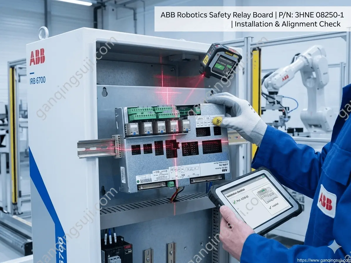
Furthermore, leading automation teams have completely abandoned grease-stained paper manuals during field commissioning. Elite automation providers now manage field replacements through rugged industrial tablets running automated validation software. The field technician simply scans the matrix barcode on the safety relay board package, which instantly populates the tablet screen with the exact wiring schematic, terminal assignments, and correct screw torque ratings for that specific robot series.
The software forces the technician to verify each terminal connection step-by-step and manually input live multimeter voltage readings before allowing the system to proceed. Once verified, the digital system logs the component’s unique serial number directly into the facility's Asset Lifecycle Management software, creating a permanent, audit-ready maintenance record that proves the safety system has been restored to full compliance.
4. B2B Sourcing Strategies for Critical Safety Electronics
When an internal relay suffers permanent hardware failure or contact degradation, field repair is rarely allowed or recommended, because safety-critical electronics must be calibrated and tested under strict laboratory conditions to maintain insurance and safety certifications. Therefore, the priority shifts entirely to reducing your plant's Mean Time to Repair through a smart component sourcing strategy.
To insulate production schedules from volatile factory lead times, warehouse procurement managers should build proactive relationships with an experienced industrial distributor specializing in top-tier European robotics hardware and control components.
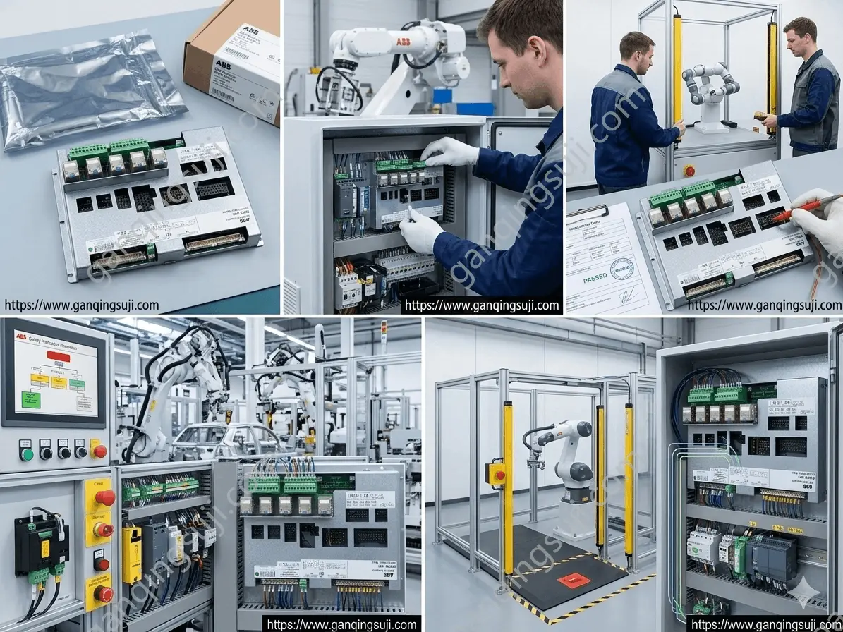
When evaluating a potential supply partner, purchasing departments should evaluate candidates based on three non-negotiable operational capabilities:
● Certified Anti-Static Packaging: Sensitive industrial circuit boards must always be stored and shipped inside premium, heat-sealed anti-static protective bags. The board should be cradled inside form-fitting, shock-absorbing pink foam layers inside a sturdy cardboard container. Undetected static discharge during shipping can subtly weaken microcontrollers, leading to unexpected field failures weeks after installation.
● Verifiable Serial Traceability: Verify that the distributor provides clear serial number data. This guarantees you are purchasing a pristine factory unit rather than a cleaned-up, low-quality module pulled from a decommissioned automotive salvage line.
● True On-Shelf Inventory: When an automotive or packaging assembly cell is down, waiting twelve to sixteen weeks for standard factory production lines is out of the question. Your chosen spare parts distributor must offer documented, same-day dispatch for mission-critical parts.
5. Summary
Clearing an intrusive robot safety fault requires a systematic approach that blends precise electrical troubleshooting with smart, proactive sourcing. By tracking onboard LED status arrays, validating dual-channel input voltages, and utilizing modern laser alignment and digital verification checklists during installation, you can maximize the operating lifespan of your electronics controller assembly. When a hardware replacement is finally required, ordering through a verified distributor ensures your machinery returns to the factory floor safely, quickly, and in full compliance with international safety protocols.